Ab3d.DXEngine Users Guide
Ab3d.DXEngine Deep Dive
In this article I will dive deeply into how the Ab3d.DXEngine renders the 3D scene.
There are many ways to use the DXEngine and to define the 3D scene. To make this article easier to understand, I will describe the rendering process by assuming that we want to show a simple 3D scene with two 3D objects (using two GeometryModel3D and a DirectionalLight) and we are using a DXViewportView to show the 3D scene.
First, I will show how a 3D scene that is defined by WPF objects is converted into DXEngine's SceneNodes. Then I will describe how those SceneNodes are rendered.
After reading this article, you should get an in-depth knowledge of how the 3D scene is rendered and which objects are created to make this possible. This will allow you to understand how to manually create SceneNode objects and how to manually change the rendering process to create advanced rendering effects.
Let's start with the following DXViewportView schema.
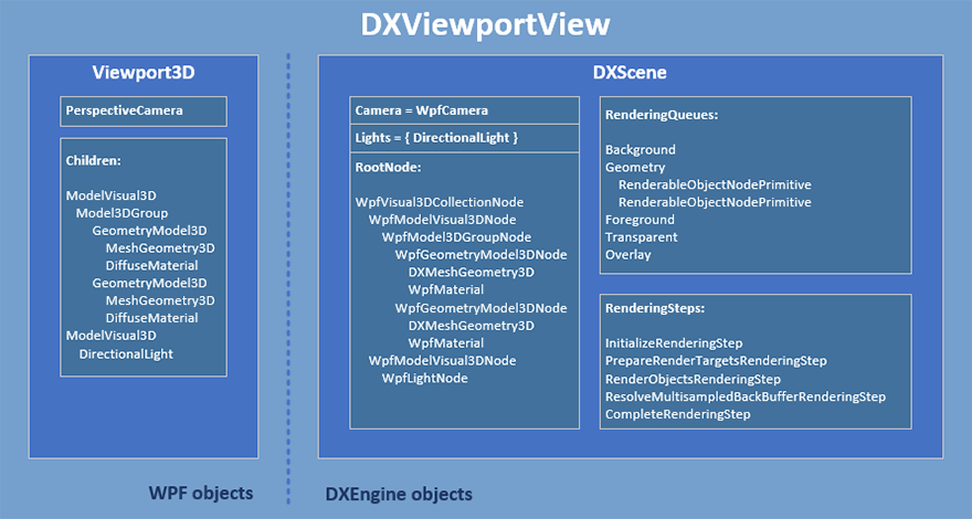
The schema is divided into two main parts. On the left are the WPF objects under Viewport3D object that defines the 3D scene. The right side shows the DXEngine objects under the DXScene object.
The 3D scene under Viewport3D is defined by 2 GeometryModel3D objects each with its own MeshGeometry3D (defines positions and triangles of the mesh) and DiffuseMaterial. There is also one DirectionalLight that provides illumination and a PerspectiveCamera.
Part I - DirectX rendering
To render this 3D scene with DirectX, the DXEngine needs to convert the scene objects into DirectX objects and commands. The required DirectX objects are:
- vertex and index buffers that define meshes,
- constant buffers that define properties that are sent to shaders (camera and light information, object transformations and material properties),
- rendering state objects (BlendState, RasterizerState, etc.).
When those objects are defined, then DirectX draw commands can be issued. Each draw call usually renders one 3D object to the scene (except for object instancing and similar cases). Each draw call requires a few DirectX API calls where DXEngine needs to set the used vertex and index buffer, constant buffers, shaders and rendering state objects. When rendering many 3D objects this may create a lot of work for the CPU and limit the rendering performance. Therefore DXEngine tries to optimize this process as much as possible with preparing as much data upfront, with using caching and rendering in multiple threads. To communicate with DirectX API, the DXEngine uses SharpDX.
Now that we know what the final goal of the DXEngine is, we can dig into the steps that are required to achieve it.
Part II - The Update phase
The first step that is done by the DXEngine is to convert the WPF objects into DXEngine objects. This is done in the Update phase and is started in the DXViewportView's Update method.
The Update method is automatically called from the CompositionTarget.Rendering event handler (this event handler is called after each WPF frame is rendered). It is possible to disable the automatic calling of the Update method by setting the DXViewportView.IsAutomaticallyUpdatingDXScene property to false.
The Update method first gets the scene's camera. To do this the WPF's PerspectiveCamera is converted into a WpfCamera (defined in the Ab3d.DirectX.Cameras namespace and in the Ab3d.DXEngine.Wpf assembly). This camera uses the properties of the PerspectiveCamera to calculate the view and perspective matrices that are needed for DirectX rendering. The class also subscribes to PerspectiveCamera's change events so that each time the PerspectiveCamera is changed, the WpfCamera can be changed and rendering a new frame can be issued. The created WpfCamera is assigned to the DXScene.Camera property. This property can be set to any object that implements the ICamera interface. Simply said, this means that the camera needs to provide the view and perspective matrices. You can create your own class that does that or use the MatrixCamera from the Ab3d.DirectX.Cameras namespace.
Than DXEngine is going through the Viewport3D.Children collection to convert the WPF 3D objects into SceneNode objects (actually objects derived from SceneNode) and assigning them to the DXScene.RootNode property.
The first object that a is created is a WpfVisual3DCollectionNode object (derived from SceneNode) that is created from a WPF's Visual3DCollection objects (used for Viewport3D.Children collection). The WpfVisual3DCollectionNode knows how to read the collection of Visual3D objects and convert the child objects into SceneNodes. Also, the WpfVisual3DCollectionNode can react to changes in the Visual3DCollection.
The first object that a is created is a WpfVisual3DCollectionNode object (derived from SceneNode) that is created from a WPF's Visual3DCollection objects (used for Viewport3D.Children collection). The WpfVisual3DCollectionNode knows how to read the collection of Visual3D objects and convert the child objects into SceneNodes. Also, the WpfVisual3DCollectionNode can react to changes in the Visual3DCollection.
The next DXEngine object is created from the first child in the Viewport3D.Children collection. In our sample that is shown in the DXViewportView schema, this object is a WpfModelVisual3DNode - created from a ModelVisual3D object. WpfModelVisual3DNode can read the ModelVisual3D.Transform property. It also keeps the Bounds property up to date - it defines the bounding box of its child objects. The WpfModelVisual3DNode can also create child SceneNodes from ModelVisual3D.Content and from ModelVisual3D.Children properties. It also monitors the changes in the original WPF object.
In our case, the WpfModelVisual3DNode creates a WpfModel3DGroupNode because a Model3DGroup object is assigned to a ModelVisual3D.Content property. WpfModel3DGroupNode is very similar to WpfModelVisual3DNode because it also checks the Transform property, sets the Bounds and monitors the Children collection.
And then we finally came to two objects that define something that is actually visible on the screen. The Model3DGroup.Children collection contains two GeometryModel3D objects that are converted into two WpfGeometryModel3DNode.
The WpfGeometryModel3DNode first gets the MeshGeometry3D object from the WPF's Geometry property and converts it into a DXMeshGeometry3D object (this object is not derived from SceneNode). The DXMeshGeometry3D reads the mesh data and creates a DirectX vertex buffer (array of positions, normals, and texture coordinates) and a DirectX index buffer (array of triangle indices). It also monitors the MeshGeometry3D for changes.
Then the GeometryModel3D.Material and GeometryModel3D.BackMaterial (when set) properties are converted into a WpfMaterial object. The WpfMaterial object is derived from the DXEngine's Material class. It implements many interfaces that provide data about the material (that data is then read by the used DXEngine's Effect).
Then the GeometryModel3D.Transform property is read and Bounds value is set to the bounding box of the mesh (transformed by the transformation).
After all the required data are prepared, the WpfGeometryModel3DNode can execute its main task - create objects that are derived from the RenderablePrimitiveBase class and add them to the correct RenderingQueue. This is done in the overridden CollectRenderableObjects method.
RenderingQueues are collections that contain objects derived from RenderablePrimitiveBase object. Each RenderablePrimitiveBase object defines the RenderGeometry method. This method actually does the drawing - it executes the DirectX calls that binds the DirectX buffers, sets the required states and issue the DirectX draw call. Usually, one RenderablePrimitiveBase executes one draw call. The goal of RenderablePrimitiveBase objects is to have all the required data for draw call organized in a simple and efficient way so that the rendering process can be as fast as possible.
In case of WpfGeometryModel3DNode, the CollectRenderableObjects method can create two RenderableObjectNodePrimitive objects. One is created when Material property is set and other when BackMaterial property is set. Note that even when BackMaterial is the same as Material, this requires two draw calls (two RenderableObjectNodePrimitive objects) because the normals need to be flipped when rendering the triangles for the back material.
When iterating the WPF 3D objects hierarchy, the DXEngine also collects the lights. Each found WPF light is converted into a WpfLightNode object (also derived from the SceneNode object). The WpfLightNode object can read WPF light properties. It also subscribes to the changes of the original WPF light object. The WpfLightNode object checks the type of the light and based on that creates a DXEngine light object (an object that implements ILight interface) - in our case a DirectionalLight object (from Ab3d.DirectX.Lights namespace) is created. This object implements the ILight, IDirectionalLight and IShadowCastingLight interfaces. Based on which interfaces are implemented by the light objects, the DXEngine knows what type of lights are used in the 3D scene. This is used to set appropriate values in the constant buffers. What is more, when a simple 3D object is rendered (with standard material and no instancing or any other advanced effect) and when there are only three or less directional lights, then DXEngine can use a higher performance directional light shader. When more directional lights, a point light or a spot light are used, then a more complex shader needs to be used. All the created lights are added to the DXScene.Lights list.
When all the WPF 3D objects are converted into DXEngine objects than the update phase is complete. This phase can be also manually invoked by calling DXViewportView.Update method (that method calls the DXScene.Update method).
After the update phase is complete, the DXEngine has gathered all the required data so that the render phase can begin. But before I describe how DXEngine performs the rendering process, let me first give you a few more information about the RenderingQueues.
Part III - RenderingQueues
RenderingQueues have multiple purposes in the DXEngine:
- The main purpose is to improve rendering performance. This is done with collecting as much data that are required for one DirectX draw call to a collection of simple objects (derived from RenderablePrimitiveBase object). This greatly simplifies the rendering process and lowers memory usage. That significantly improves rendering performance.
- Provide the rendering data in a standard way so that even a custom rendering code or a custom effect can use the data without having any knowledge about the special features of the SceneNode that was used to prepare the data.
- RenderingQueues provide a top level order or rendering. First, all objects from the first RenderingQueue are rendered in the order as they are present in the first RenderingQueue. Then the objects from the next RenderingQueue are rendered. For example, this is used to make sure that all non-transparent objects are rendered before all transparent objects.
- The DXEngine can reorder individual objects inside a RenderingQueue in such a way that the number of required DirectX stat changes is minimal. The reordering is done with grouping objects with similar materials together so that the same constant buffers or shader states can be reused to render as many objects as possible. This improves rendering performance. Note that RenderingQueue that contains transparent objects, this optimization is skipped because the rendering order of transparent objects is important and must not be changed by the DXEngine.
- RenderingQueues can be used to organize objects into groups - with using a custom RenderObjectsRenderingStep with FilterRenderingQueuesFunction and OverrideEffect, the objects in each RenderingGroup can be rendered with the specified effect that is defined in the OverrideEffect. More about that later.
- Once RenderingQueues are prepared in the Update phase, they are not changed by the DXEngine until the next update phase. This means that during the rendering phase they are immutable and therefore can be safely used for multi-threaded rendering where each thread renders part of the objects in the queue.
By default, the DXEngine defines the following RenderingQueues:
- Background
- ComplexGeometry
- StandardGeometry
- OtherGeometry
- LineGeometry
- Foreground
- Transparent
- Overlay
If the object has a transparent material (if StandardMaterial.HasTransparency is true), then it is put into the Transparent RenderingQueue. This way it is rendered after the opaque objects.
When transparency sorting is enabled (DXScene.IsTransparencySortingEnabled is true), then the objects in this RenderingQueue are sorted by their distance to the camera so that objects that
are farther away are rendered before objects that are closer to the camera. The distance is calculated as the distance from the camera's position to the center position of the object's bounding box.
Opaque objects are distributed between ComplexGeometry, StandardGeometry and OtherGeometry rendering queues.
If an object has many triangles (by default more than 100000 - this is defined by the DXScene.MeshTriangleIndicesCountRequiredForComplexGeometry)
or many 3D lines positions (more than 20000 - defined by DXScene.LinesCountRequiredForComplexGeometry) or when object instancing is used,
then the object is put into the ComplexGeometry rendering queue. This way its draw call is issued as soon as possible so that the graphics card can start rendering complex objects as soon as possible.
Objects with StandardMaterial or WpfMaterial are put into the StandardGeometry rendering queue. This rendering queue support DirectX commands caching and multi-threading.
Objects with other materials are put into the OtherGeometry rendering queue - this is used for effects that do not support multi-threading.
3D lines that are not put into the ComplexGeometry rendering queue are put into the LineGeometry rendering queue.
All RenderingQueues are defined as properties on the DXScene object (BackgroundRenderingQueue, ComplexGeometryQueue, StandardGeometryQueue, OtherGeometryQueue, LineGeometry, ForegroundRenderingQueue, TransparentRenderingQueue and OverlayRenderingQueue).
You can also add your own rendering queues or remove some of them by using AddRenderingQueueAfter, AddRenderingQueueBefore and RemoveRenderingQueue methods.
The easiest way to change the RenderingQueue for WPF objects is to set the CustomRenderingQueue as a DXAttribute to a GeometryModel3D or Visual3D - for example:
myModelVisual3DObject.SetDXAttribute(DXAttributeType.CustomRenderingQueue, dxScene.OverlayRenderingQueue);
This line sets the CustomRenderingQueue attribute to the myModelVisual3DObject and specifies that all child 3D objects of the myModelVisual3DObject should be put into the OverlayRenderingQueue.
For MeshObjectNode objects you can change the RenderingQueue by setting the CustomRenderingQueue property (available from version 3.3). For other SceneNode objects, you will need to override the CollectRenderableObjects method - there you will need to create the objects derived from RenderablePrimitiveBase object and add them to the RenderingQueue of your choice.
Now that the purpose of RenderingQueues is more clear, we can move on to the rendering phase.
Part IV- The Rendering phase
The actual rendering process in the DXEngine starts in the DXViewportView.RenderScene method. This method is automatically called from the CompositionTarget.Rendering event handler (it can be also called manually). This method calls the DXScene.RenderScene method.
And in the DXScene.RenderScene method the rendering is performed with executing the rendering steps that are defined in the DXScene.RenderingSteps collection. By default the following rendering steps are defined in the RenderingSteps collection:
- InitializeRenderingStep
- PrepareRenderTargetsRenderingStep
- RenderObjectsRenderingStep
- ResolveMultisampledBackBufferRenderingStep
- RenderingStepsGroup
5a. PreparePostProcessingRenderingStep
5b. RenderPostProcessingRenderingStep
- CompleteRenderingStep
Each specified RenderingStep is its own class that is derived from the RenderingStepBase and override the abstract OnRun method. This method is called with a RenderingContext object that provides all the information about the current rendering context: current frame number, used DXScene, Viewport, Camera and many more properties that are relevant for the rendering process. Those properties also include the current and the final back buffer, their descriptions, render target view and depth stencil view. For example, the RenderObjectsRenderingStep renders the object to the back buffer that is set to the CurrentBackBuffer property in the RenderingContext. So, to render to a custom back buffer, you can change the value of the CurrentBackBuffer before the RenderObjectsRenderingStep is executed.
The first rendering step (InitializeRenderingStep) initializes the RenderingContext - it sets the current and final back buffer, sets Viewport and Camera; it also reorders the objects inside RenderingQueues if this is needed (to group them by material and required DirectX state changes).
Then the PrepareRenderTargetsRenderingStep is executed. This step reads the current back buffer and sets it to be used by the DirectX (sets it to DirectX OutputMerger). Then it clears the back buffer with the background color. Finally the state of the ContextStateManager that caches and optimizes the DirectX state changes is reset.
The third rendering step is the RenderObjectsRenderingStep. As the name says, this rendering step renders all 3D objects. This is done with going through all RenderingQueue objects and render all objects in each queue. When multi-threading is enabled and if there are many objects in a RenderingQueue, then RenderObjectsRenderingStep uses multiple threads and dynamically dispatches the work so that all the threads are used as much as possible.
RenderObjectsRenderingStep object can be customized in many possible ways. With setting FilterLightsFunction you can define which lights from the scene will be used to render the object. To filter which objects will be rendered you can use the FilterRenderingQueuesFunction or FilterObjectsFunction. The FilterObjectsFunction gives you much more control then FilterRenderingQueuesFunction but because this function is called for each object in each rendering queue, using this function can decrease the performance. If using FilterRenderingQueuesFunction significantly reduces the performance, then it is better to group your 3D objects into different RenderingQueue and use FilterRenderingQueuesFunction instead.
Apart from filtering, RenderObjectsRenderingStep object can be further customized by setting the following properties:
- OverrideEffect - when set, then all objects will be rendered with the specified effect instead of the effect that is inferred from the material. For example, you can use SolidColorEffect to render all objects with a single color.
- OverrideStandardEffect - similar as OverrideEffect but it will only override the standard effect (used to render WPF objects and objects with StandardMaterial) but not 3D lines, instancing and other advanced effects.
- OverrideBlendState - when set, then a custom DirectX blend state will be used to render the objects. This can be used to achieve some special effects like an additive or subtractive blending.
- OverrideDepthStencilState - when set, then a custom depth stencil state will be used. This can be used when your special effect needs to write to a stencil buffer.
- OverrideRasterizerState - when set, then a custom rasterizer state will be used. This can be used to provide custom culling (none, back or front), use custom depth bias or some other effect.
Because you can add multiple instances of RenderObjectsRenderingStep to the rendering steps and because you can use filters and override rendering settings, you can easily create custom effects where some objects are rendered with some effect and others with some other effect.
Let's finish the description of the RenderObjectsRenderingStep and proceed to the next rendering step. This is the ResolveMultisampledBackBufferRenderingStep. This rendering step is used when MSAA (multi-sampled anti-aliasing) is used. For example, when 4x MSAA is used (by default) then instead of rendering each pixel once, the pixel is rendered 4 times each time with small sub-pixel offset. This produces 4 times the resolution of the image. But because the screen does not support subpixels, the increased MSAA image needs to be resolved (downsampled) into the image with the final resolution. This rendering step does that.
A next rendering step is actually a group of rendering steps that are used to render post process effects. Usually, this rendering step group is disabled, but when there are any post processes then the two child rendering steps execute the post processes.
The last rendering step in the standard DXEngine rendering pipeline is CompleteRenderingStep. This rendering step, as its name suggests, completes the rendering of one frame. There are two ways in which this can be achieved. The way that is used depends on the value of the DXViewportView's PresentationType property).
When DirectXOverlay PresentationType is used, then DXEngine is using a DirectX SwapChain. In this case, this rendering step calls the DirectX Present method. This method tells the DirectX that we have finished sending all the draw commands for this frame and that DirectX can continue rendering the scene in the background and when rendering is complete it can show the rendered image to its part of the screen (its hwnd). The Present method completes immediately and the application does not need to wait until the 3D scene is rendered.
When DirectXImage is used as a PresentationType value or when we are rendering to a bitmap, then the code in the CompleteRenderingStep first need to wait until the graphics card finishes rendering the scene (this is also a reason why the DirectXOverlay can be significantly faster than the DirectXImage). After the waiting is complete, then the rendered image can be "sent" to the WPF composition engine (using D3DImage) or copied to the main CPU memory (so it can be transformed to bitmap).
And this concludes the rendering process. I really hope that this gave you a much better understanding of the rendering process. This should also show you many possible ways to extend and customize the rendering process.
If you want to learn more, then I highly recommend you to get known with DXEngine's Diagnostics Window. It can be opened in the Main DXEngine sample project by clicking on the Diagnostics button. The Diagnostics Window can be also opened in your application with using the DXEngineSnoop tool (installed into Tools folder). This tool will allow you to connect to your application and get many information and data from the DXEngine rendering process. For example, you can get all the created SceneNode objects, the content of the RenderingQueues, RenderingSteps and many more - read the Diagnostics section to get more information about using diagnostics tools.
The next step in getting some additional information on how DXEngine works is to check the samples in the Advanced section - they show how to work with low-level DXEngine objects and reveal some additional information.
You can also check the samples for WinForms. This will show you how to use DXEngine without using the DXViewportView - creating DXDevice and DXScene manually.
And if you have any questions, please write the question to the Ab3d.DXEngine forum or contact us.